Winston-Lutz test
Read about the Winston-Lutz test from QAserver’s user manual, otherwise you will not understand what I am talking about.
You will need Elekta’s BB or any other kind of similar phantom. If you don’t have micrometer screws on your phantom, you can use HexaPOD for positioning.
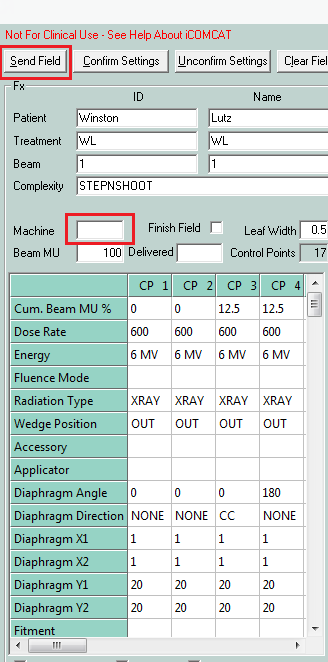
Import these two beams to Service (see Getting started):
These are automated Step and shoot beams that will speed up your acquisition. When the beam is loaded in Integrity, prepare iView for 8-image sequential acquisition, then run the beam. All will be done automatically.
Both beams contain minimalistic sequences of gantry/collimator angles that are just enough to find the MV isocenter. One beam uses collimator pairs 0/180, and the other 90/270. Doing measurements with both beams will help you determine if the focal spot has any GT deviation.
If you are doing the test with 6 FFF or 10 FFF, or for SRS, go with smaller beams. I prefer to use a field size of 2 cm x 2 cm. If you don’t like this field size, you can always change it in iCOM CAT.
Influence of dose rate on focal spot position
Although the Field size module is more appropriate for this measurement, it is easy to see with the WL module as well what is going on with the field CAX when dose rate is changed. Put gantry and collimator to 0. Put the BB into the approximate center of the field. Use a field of size 2 x 2, but not more than 5 x 5. Collect EPID images at several dose rates. The diagrams below show how the CAX is drifting towards A when dose rate is increased for 6 MV and 6 FFF. Dose rate was increased in steps of 50 MU/min. The Variable Dose Rate mode was used to achieve this.
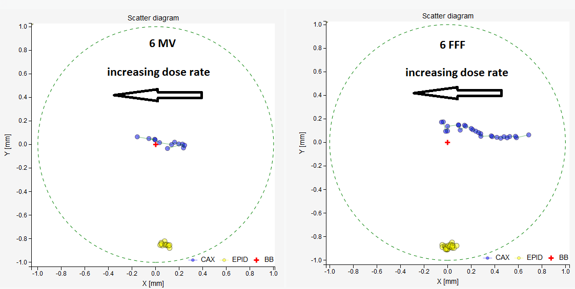
The drift of field CAX with increasing dose rate. On the left 6 MV, on the right 6 FFF. The red cross is the BB, which is stationary. Yellow dots are EPID centers, which are also stationary. Blue dots are field CAX. This is a BEV diagram, x is in the AB direction, y in the TG direction.
The same can be seen on the regular Winston-Lutz test with 8-image acquistion. See the image below.
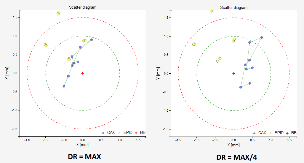
The effect of dose rate on the focal spot position detected with the ordinary 8-image WL test. On the left, images acquired with max dose rate, on the right, with a quarter dose rate. Both with 6 FFF. At max dose rate the beam shows 0.2 mm displacement towards A, and at quarter max dose rate 0.5 mm displacement towards B.
This drift is approximately 0.4 mm for 6 MV and 0.8 mm for 6 FFF. For the latter it is clinically significant and one should decide how to adjust beam steering. I like to use max dose rate at all times. For SRS in particular, the dose rate will be max almost all the time, so the beam should be accurate near max dose rates.
Note
You may get artifacts when using FFF beams. In this case you can clear the edges of the image with the clip box option. Image below shows typical FFF artifacts on older systems. Additionally, max dose rate for FFF beams may flatten out your field. In this case use lower dose rates.
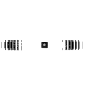
6 FFF image of the BB with lateral artifacts. Only present with older imagers/software.
End-to-end WL test
The point of an end-to-end test is to repeat the same steps as you would during clinical routine. In our case we image the BB with XVI, calculate shifts, apply the shifts with micrometer scres (you can even use HexaPOD for positioning), and then we treat it.
For better CBCT image of the BB prepare a special reconstruction preset. You can shrink the reconstruction window and increase the resolution, but be careful because some combinations don’t work. Change the reconstruction voxel size to, say, 0.5 mm or 1 mm. ReconstructionDataType should be set to float, and ProjectionDownSizeFactor should be set to 1.
Put the BB on the couch. Align it with the lasers. Make a CBCT scan. Register the scan with the reference image. Try to be accurate. Make the shifts with micrometer crews.
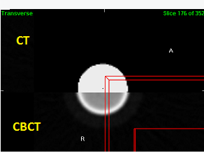
A CBCT image of the BB is well aligned with the reference CT image.
Repeat the CBCT scan and re-register. If you used HexaPOD for positioning, then the residual error will tell you how accurate your couch movements are. If the residual error is below 0.1 or 0.2 mm, proceed with the test, otherwise shift the BB and re-scan.
Once the BB is in position, treat it with a sequence of 8 beams. I normally use this sequence.
Gantry |
180 |
180 |
270 |
270 |
0 |
0 |
90 |
90 |
Collimator |
90 |
270 |
270 |
90 |
90 |
270 |
270 |
90 |
Or a similar sequence with collimator angle pairs 90/270. Just use the supplied fields above.
In iView, you can set automatic IMRT acquisition with 8 frames, so that both the linac and iView are automated.
What can the results teach you? Well, since you used XVI to position the BB, you will see how accurately XVI displays the isocenter on the image, ie. how accurate your tumor targeting will be. Not taking couch positioning into account, unless you used HexaPOD.
Here is an example of an almost perfect result. Each blue dot is the field CAX, and the red cross is the BB center. Blue dots are spread out longitudinally because of the gantry sag (1.2 mm). Which is normal! Neighboring points (opposite collimator angles) are close together which means that there is little collimator asymmetry or wobble. And the cloud of points is not displaced laterally which means that your beam is well centered. There is just a small average error in the longitudinal direction (0.2 mm), which is probably caused by HexaPOD and XVI together. HexaPOD’s contribution to the error can be estimated by repeating the CBCT scan and re-registering the images, as said before.
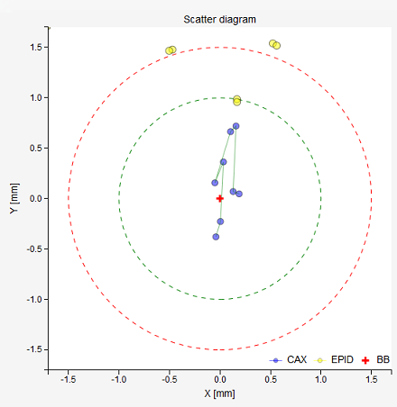
A perfect result for Agility on Elekta VersaHD.
Here is a table of the results:
Image |
Δx [mm] |
Δy [mm] |
R [mm] |
1 |
-0.04 |
-0.38 |
0.38 |
2 |
0.0 |
-0.23 |
0.23 |
3 |
0.03 |
0.36 |
0.37 |
4 |
-0.05 |
0.16 |
0.16 |
5 |
0.1 |
0.66 |
0.67 |
6 |
0.16 |
0.72 |
0.74 |
7 |
0.13 |
0.07 |
0.15 |
8 |
0.19 |
0.05 |
0.2 |
A little less perfect is the result of the same test with the same BB position, only that 6 FFF was used. See below. The cloud has a substantial lateral displacement. Make no mistake, this deviation is not caused by the positioning of the BB. It is caused by improper beam steering settings. It can be easily fixed with 2T, 1R/1T. Please note that this displacement varies with dose rate! If I used lower dose rate, the results would be even worse.
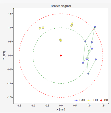
A bad result for 6 FFF. The beam has a huge lateral deviation.
Here are the results in this case:
Image |
Δx [mm] |
Δy [mm] |
R [mm] |
1 |
1.25 |
-0.14 |
1.26 |
2 |
0.98 |
-0.65 |
1.18 |
3 |
0.93 |
-0.14 |
0.94 |
4 |
1.1 |
0.48 |
1.2 |
5 |
1.21 |
1.03 |
1.59 |
6 |
0.87 |
0.51 |
1.01 |
7 |
0.79 |
-0.26 |
0.83 |
8 |
1.11 |
0.25 |
1.14 |
And the proposed shifts of the BB. Calculations show that the BB is almost in the right place, so the deviation is not caused by BB positioning, but by the beam itself.
LAT |
LONG |
VRT |
0.04 mm → LEFT |
0.14 mm → IN |
0.03 mm → UP |
Note
Lateral beam deviations can be clinically important. Particularly when treating well positioned anatomy like the spine with high doses. Longitudinal deviations in this case are not as important, but unlike lateral deviations longitudinal can be compensated by XVI. If you think about it, if your 6 MV beam has a 0.5 mm displacement towards G, then flexmap calibration will teach XVI that the isocenter is positioned 0.5 mm towards G. So no miss-treatment will occur (well, not exactly … there is another effect that comes up with collimator rotation if the focal spot it not in the right position).
Non-end-to-end WL test
Some people like to reverse the procedure and position the BB by minimizing BB shifts, then they make a CBCT scan, and the registration error tells them what the difference between imaging and treatment coordinates is. You can do this if you’d like. I only do this after flexmap calibration, because in that case that is a must.
Anyway, once the BB is in the average 6 MV isocenter, you can repeat the test with other energies, while you are at it. That way you will instantly know if all other energies are “aligned” with 6 MV. Below is an example.
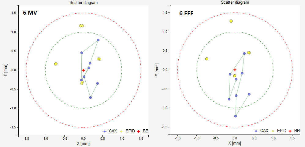
On the left, 6 MV. The BB is in the perfect position. No significant deviations of the beam are noticed. There is some MLC asymmetry. On the right, 6 FFF. It can be seen that the 6 FFF beam is shifted towards T with respect to 6 MV.
Effect of focal spot position on WL test
Position the BB into the average MV isocenter using the minimalistic set of images with collimator angles 0/180. Once the BB is in position, repeat the test with a similar sequence, except that the collimator angles should be 90/270. Compare the results in “Moving the BB into the isocenter”. If they differ a lot in the longitudinal direction, then it may be that the focal spot of your beam is not where it should be, ie. on the collimator axis of rotation. Of course, there are other influences like diaphragm/MLC sag, but usually these are not so severe. See 1. If you would like to learn more about this effect, read Focal spot position, collimator asymmetry.
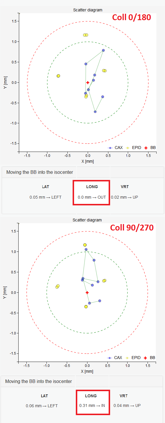
Top, results for 6 MV are ideal when 0/180 collimator angles are used in the sequence. Bottom, the BB in the same position, imaged with the same beam, but with 90/270 collimator angles. This is caused by improper GT beam steering.
- 1
Chojnowski JM, Taylor LM, Sykes JR, Thwaites DI, Beam focal spot position determination for an Elekta linac with the Agility® head; practical guide with a ready-to-go procedure, J Appl Clin Med Phys. 2018 Jul;19(4):44-47
Couch axis of rotation and WL test
If you don’t use couch rotations, you can skip this part. But, if you are doing radiosurgery, then listen hard.
We know that gantry sag is about 1.2 mm. What happens if we align the couch axis of rotation with the optical crosshair, that is, with the collimator axis of rotation at gantry 0? Well, the BB will be positioned 0.6 mm away from the collimator axis of rotation. When we rotate the couch, therefore, the BB will not remain stationary like it should. It will instead rotate about the collimator axis of rotation. And when gantry is at 180, the distance between CAX and BB will increase to 1.2 mm, which is too much. The same effect can be caused by GT beam deviations (improper Bending Fine), when your beam is missing the mechanical axis. Anyway, the best way of assuring a good WL result with couch rotation is to deliberately align the couch axis with the average MV isocenter.
Note
Adjustment of couch axis of rotation is a worthwhile task. You will learn a lot by doing it! Read also: 2.
I do this:
Do the normal end-to-end WL test.
Put gantry to 0 and collimator to 0.
Rotate the couch and acquire an image of the BB for each angle. I use these couch angles: -90, -45, 0, 45, 90. Be sure to go back and see if there is any hysteresis. There will be!
Here is an example measurement. Because the couch axis is well adjusted to the average MV isocenter that is represented by the BB, the BB moves about moderately. You can see that the path of the BB forms a semi-circle. The center of the inscribed circle will define the couch axis. What we are interested is how far the couch axis is from the MV center.
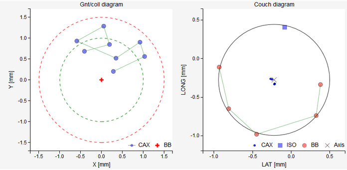
Couch rotation test. Image on the left shows the usual WL test result. You can see that the MV isocenter and the BB do not match in the longitudinal direction. This will not cause problems when measuring the couch axis position, since we can transfer the position of the MV isocenter and the BB position onto the epid independently of the position of the BB. On the right image you can observe how the BB moves about when the couch is rotated. The cross corresponds to the couch axis. The blue square is the position of the MV isocenter on the detector plate calculated from the left image. Red circles are BB positions. Ideally, the blue square and the black cross should coincide.
Read pyqaserver documentation on how to measure the distance between the couch axis and MV isocenter. What you can do is, you can turn the A and B screws that hold the couch to the floor, until you match the couch axis with the MV isocenter. With a couple of iterations you can better align your couch. Just keep the BB on the couch, but do not touch anything else except the screws. Do not touch the epid, because the points on the diagram are relative to the center of the epid. Read the article that I mentioned previously. If the black cross is displaced only longitudinally, then turn both screws equally in the same direction. That is usually the case. By turning the screws you are also changing the tilt of the table. This could be an issue, so be mindful.
Just another note. If the BB is too close to the axis of rotation, you will not get a clear semi-circle. In this case, deliberately displace the BB a bit.
Warning
If you position the BB with Elekta’s flexmap MV image analysis program, it will be shifted longitudinally by 0.3 mm when compared to Pylinac’s calculations. I tested it with other software as well, and Elekta is the only one that is doing it differently. So bear in mind that longitudinal position of XVI’s isocenter may be a bit shifted, and hence the couch rotations test may give a different result by up to 0.6 mm.
- 2
Matthew J. Nyflot, Ning Cao, Juergen Meyer, Eric C. Ford, Improved accuracy for noncoplanar radiotherapy: an EPID-based method for submillimeter alignment of linear accelerator table rotation with MV isocenter, J Appl Clin Med Phys. 2014 Mar 6;15(2):4682